
Motors
We’ll start with the basics and build up from there. A servo motor system consists of a motor, some sort of rotary feedback device, and a motor controller that gives the motor commands. Most servo systems are built around rotary motors, so that’s what we’ll focus on now, but the same principles apply to a linear actuator.
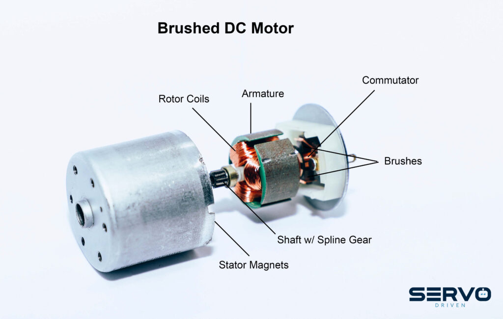
The most common motors in servo systems are either AC motors or DC motors. AC motors are powered by a sinusoidal voltage source (Alternating Current) where DC motors are power by direct application of a voltage (which induces a current in the windings, hence Direct Current, motors). Whether AC or DC, the motor consists of a stator (stationary part – usually the outside “shell” of the motor) and the rotor, or the rotational element that does all of the work.
Regardless of the motor type, both the stator and the rotor have a series of magnetic fields and they develop torque by virtue of having one of the magnetic fields rotate around the perimeter, usually the stator, which interacts with magnetic fields on the rotor causing it to rotate. The rotor will usually have a shaft on it that sticks out of one (or both) ends of the motor, so that useful mechanical things, like gears can be attached to the motor.
Feedback
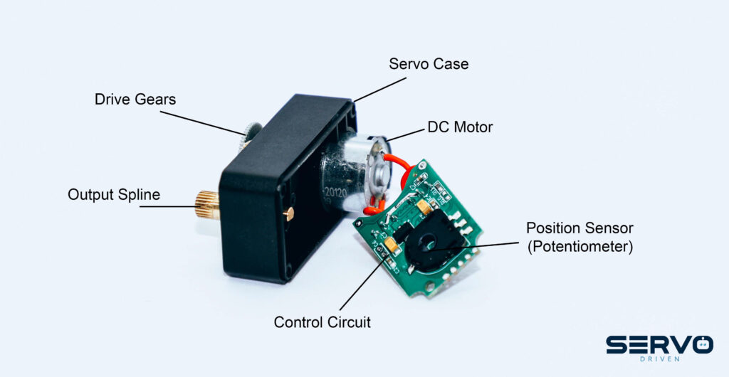
In order for a motor to act as a servo motor it must contain a feedback device, which is often attached directly to the back of the motor, or geared off of the output shaft. Feedback allows the controller to get real time information on the rotor position to make sure it’s moving as it was commanded to move. The feedback can be as simple as a series of hall effect switches evenly spaced on a PCBA mounted to the back of the motor. More commonly, for hobby servo motors, a rotary potentiometer or even an encoder could be used. By way of illustration here is a partially disassembled servo motor that is available to the hobbyist. Note that the feedback device (a potentiometer in this case) is connected to the main shaft via a gear set. This means there will be some backlash in the system, but likely not enough to cause any serious problem. The servo IC is used to interpret the feedback signal and may also convert it through an A/D converter. It also likely provides the drive signals to the motor. There are a lot of potential functions available on servo IC’s, so it depends on the servo IC and the controller that is being used. Most functions for reading feedback and controlling the motor come from the controller, but sometimes they are split between the motor and the controller. It just depends on the manufacturer’s servo motor “ecosystem”.
Controllers
There are probably as many variations in controllers as there are in servo motors, but the basic function is all the same. In the industrial world, they are known as programmable logic controllers (PLC’s) so that is a term you may run into. Basically, the controller is programmed to do some very specific functions and it often has several different inputs available. It may have a few analog inputs and a few digital inputs so that things like limit switches, a load cell, or light detection can be used along with the motor position information to make it more useful. In the hobbyist world some of the popular controllers are Raspberry Pi, Arduino, Beaglebone and Adafruit. Of course, the other things the controller needs to do is read the status of the servo motor; what is its current position and speed; and also send signals back to the motor drive circuitry to tell it to keep moving, stop, or reverse direction depending on the function that it was programmed to do. The controller often will also supply power to the servomotor.
Special Wiring Considerations
As a servo system evolves and more devices and controllers get added, there may come a time when investing in some wiring clean-up will simplify the installation and, in some cases improve performance. We will talk about two options that may be available depending on the system design. The first and most straightforward is known as daisy-chaining. This can work on the power side or on the signal side.
Imagine you have designed a system which is powered by the USB port of your laptop. You decide that you need to duplicate that system two more times, but you have run out of USB ports to connect to. Somewhere on that first controller, there is a power line (often with a red wire) and a signal common, or ground (black wire). Daisy chaining is as simple as finding the power and ground lines on the #1 controller and run a wire to the corresponding terminals on the #2 and #3 controllers. Keep in mind that this will triple the current draw from the USB port (or whatever power source you are using), so you need to make sure that you have the capacity, but this is the basic principle behind daisy chaining.
A similar situation can arise if you have multiple controllers that are synchronized to have their servo motors performing an identical task. In this situation the commanded position or speed will be the same for all motors, so it is possible to daisy chain the control signal from the #1 controller to the control signal input on servo #2 and servo #3. Again, you need to make sure that the #1 controller signal output can drive the load and you also need to be sure that all of the motors are referencing the same ground to avoid cross-talk.
In addition to daisy chaining, another way to simplify the wiring is to use a communication bus for the controllers. If the servo system was a symphony, the #1 servo controller would be the conductor and all of the other controllers would be the musicians. Most bus protocols are designed for serial communication at TTL levels. The particulars of the command set available are determined by the bus manufacturer.
In the bus-connected scheme each servo motor/controller combination has an assigned ID. Typically, this is an 8-bit word, meaning that up to 256 nodes can be controlled using this scheme. As a practical matter some of the bus registers need some space for administrative functions, so the actual number of nodes is usually a bit less, but usually not limiting. To state the obvious, in order to take advantage of a communication bus, the controllers themselves, need to be designed to accept what is usually a two-wire control system attached to the #1 controller. In some cases the #1 controller can be your PC laptop.
As an introduction to servo motors, controllers and connectivity this subject was broadly covered but should give you an idea of how to get started in the world of servo driven motion applications. Future articles will go into more depth about particulars of motor types and other key considerations for servo control.