Whether it’s building a stair-crawler, rolling trash picker-upper, or a custom 3D printer, the magic is in the movement. And to get the movement required takes a little bit of patience and a few handy calculations to make sure the motors you select can do the job. Choosing the right motor is a matter of finding the right balance between Torque, Speed and Inertial loads. Fortunately, this is well understood and fairly straightforward. Motor manufacturers produce the necessary graphs that show how their motors are designed to perform. Once the motor performance required to do the job has been calculated, an appropriate motor can be chosen that meets those requirements and will bring the project to life.
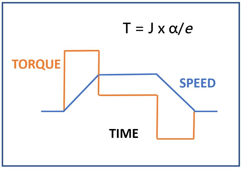
The process of defining a motor to a specific task is called motor sizing and is a fundamental part of building a servo driven system. Since this is usually an exercise that is done at the beginning of the design stage, it’s easy to forget the process if it’s not an everyday activity. This overview will serve as a refresher for some and an easy introduction for others. Foremost, a servomotor is a device to deliver power. You will remember that work/unit time is the definition of power, so we start by calculating an estimate of this requirement. For ease of standardizing motor parameters, typical calculations are designed around a trapezoidal move: a ramp up in speed from zero until the desired velocity is reached, followed by a ramp down finishing at the new desired position with a speed of zero. (Ref: Figure 1)
Recall that Newton gave us the formula that force applied over distance = work. His simple formula of F=ma applied to linear systems. For rotary systems we need to substitute T = torque in place of F; J = rotary moment of inertia in place of m; and α = angular speed in place of acceleration. It is also necessary to introduce an efficiency factor, e to accommodate mechanical and electrical losses, since we are dealing with a real system and not an idealized system.

Figure 1 Trapezoidal Move
To put this into practice, look at figure 1. The planned move profile is indicated by the blue “Speed” line which is angular speed. When doing this calculation, it is important to incorporate the total of all the inertias involved in the “J” term, so be sure to include the motor inertia along with the load inertia. The motor inertia is a published value by the manufacturer and the load inertia will need to be calculated using standard rotary inertial formulas for rotating objects. If the motor is coupled to a manufactured item (like a ballscrew for example) the manufacturer should be able to provide inertia figures as well as an efficiency factor to be used in the Torque calculation. As a rule of thumb, the ratio of load inertia to motor inertia JL/JM should be about in the range of 5:1 up to 10:1. A lower inertia ratio indicates a higher performance system and a higher ratio indicates a lower performance system. Think of it this way, a small motor will have a small inertia (and a bigger ratio between the load and the motor). If the motor tries to move a really big load, it might not have enough torque to do the job.
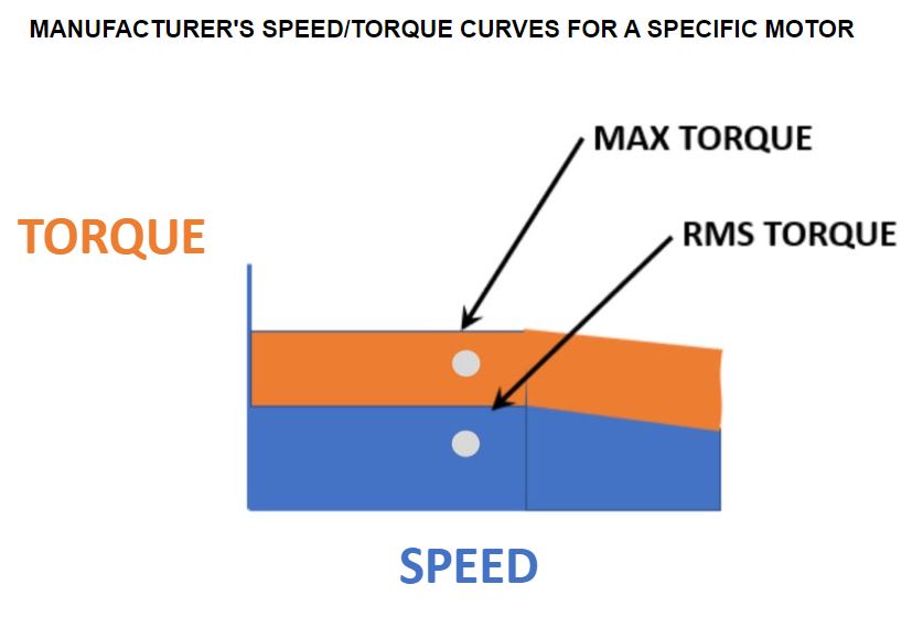
When calculating torque, it is important to calculate two values: the highest torque value expected by the system during normal operation TMAX, and the RMS value of the torque over a complete cycle, which includes any rest time during which the motor is not running, TRMS. Manufacturers publish these values as the maximum or peak torque, which can only be achieved for a very short time before overheating, and the continuous, or rated torque, which takes into account variations in torque as well as duty cycle. A successful design will have a TRMS that falls within the manufacturers’ curves for continuous operation, and will not exceed the published TMAX value. In Figure 2 the calculated design parameters are shown as pale dots which meet these criteria.

Figure 2 Target Design Plotted on Motor Speed/Torque Curve
Calculating the RMS torque value is a matter of taking each of the calculated torque values in the move profile, square them and multiply that value by the time that torque is applied. Add all those values together, divide by the total time and then take the square root of that value.
At this stage all the information is available to do a preliminary motor sizing. Using the motor manufacturer’s curves should point to a motor that can deliver the RMS torque at the intended RPM, but that does not exceed the MAX torque and also has a reasonable inertia ratio. The RPM values come from the planned move profiles that were decided early on and since the load is already calculated, the inertia ratio is known. If it turns out that a high inertia ratio is pushing the design toward a larger motor (and more costly electronics), it may be possible to use a gear set to reduce the torque requirement. The trade-off for this decision being that the motor must turn faster to achieve the same move profile as before, but the chance to make the system work with a smaller motor and electronics package can make the trade-off worthwhile.
Motor sizing is at the heart of servo-motor controlled robotics projects and there are enough variables to play with to be able to do almost any size of project. Keep the fundamentals in mind about the interplay of torque, speed and inertia and after a couple of iterations, it will become second nature.
